


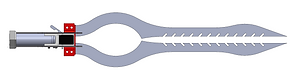
heat shields protect
and snuff excess flames
High Voltage arc electrifies blade
and ignites fuel
accepts commercial
butane canisters
fuel is dispensed
dual tips can be used a utensil.
like chopsticks.
butane flame.
for results.
ambidextrous
triggers
resin cross guard insulates both
heat and electricity


usb-c charging
See the Design Process

Defining the problem
What problem am I solving?
This project is a hands-on exercise in the engineering design process, combining CAD modeling, mechanical fabrication, and electrical integration. It also serves as a portfolio piece to demonstrate practical skills and creativity to peers and potential recruiters.
creating a basic sketch. This project stems from several gauntlets before it which were similar in nature.
Unlike gauntlets however, this project would need be incredibly space restrained, rugged in its design, and overall, a more formal engineering challenge.

Brainstorming
Where did this design come from?
After lots of brainstorming and whiteboard sketches, one of the things that was most important to us was the idea that the blade was electrified, and that it was dramatic about it. We also had the idea for dual blades, isolated electrically to get an arc to jump in-between them, which would light the fuel. You can already see some of the key ideas that made it to the final design, such as the shape of the blade, a dramatic arc point, and slits that hold chemicals to influence the color of the flame. I had also settled on butane, since I had used it in past projects, it's easy to get, and it's relatively safe, especially compared to liquid fuels.
Designing Version 1.0
Structure
The main structural element of this design is the "Enamel" Highlighted in red, this is the most complex piece, and is responsible for insulating and holding the blades in place, the two large holes are used for fixing the blade in place, either with, bolts, or eventually permanent pins. The enamel is supported by two "Tongs" which are intended to be made of carbon fiber, but won't see that until the final version, to save on costs. These tongs also support the blades, in an interlocking way, but are prevented from direct contact to the blades by the "Enamel", so that the user is not shocked. The "Tongs" are also responsible for holding the rest of the elements, such as the fuel dispensing mechanism, the electronics, and the butane canister.
PCB Mounting
The electronics PCB is mounted on the side of the handle with cutouts for both the PCB and the lever. This might compromise the strength of the handle, but it offers the best ergonomics.
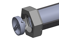
Butane Release and Canister Holding
The design of Version 1.0 includes a simple butane release mechanism that relies on a set of levers to open the canister, by pushing down on the nozzle. The butane canister is held in place by a small door at the base of the handle that rotates until it clicks open and shut, locking the canister in the handle.

Testing Version 1.0
Design Evaluation
You can see on the left that it assembled nicely, and it held everything as expected. However, the initial structural weakness of Version 1.0 was evident immediately after construction, showing the need for reinforcement. The canister holding worked really well, but I came to realize that it was quite slow, and it was easy to drop the lid when changing the canister. The PCB was also in an inconvenient location, and the wires rubbed against the canister when reloading, which would occasionally mess up the wiring.
Live Test
I decided to test its ability to dispense butane, and it did it quite effectively, but it had major leaks, shown in the demo video. A mock blade was also printed evaluate full proportions of the sword in physical form. Other than the obvious safety hazard, it did technically work, and it was time to fix things in Solidworks. I would also have to start considering how I would keep my design from melting.


Designing Version 2.0
Addressing Previous Issues
For the second version of this design, I greatly reinforced the hilt portion that holds the blades. I also started designing the hilt with the end goal of having G-10 Composite (FR-4 grade) parts on the outside, so that they could protect the weaker parts on the inside from fire while also providing structural rigidity. This design still features the PCB and controls on the side but features a new way to hold the canister. A small tab locks onto the canister, and compresses a spring, when the lever attached to the tab is pressed, the canister is ejected.

Testing Version 2.0
Spark Troubleshooting
Since the butane system worked from the last design, it mostly stayed the same and carried over. However, now I had a set of metal blades to work with, so I was more focused on getting the spark to arc between them. After assembly the blade and soldering and wiring together all of its electronics, I was having trouble getting the spark to jump the gap.
I was quite puzzled honestly, since it had been able to jump much larger gaps even in wire. I wondered if the resistance of the metal was that high, or if it was oxidized on the surface which was affecting it's conductivity. I tried sanding down the contact and arc points but when that didn't work, I tried reducing the distance until I got a spark.
After forcibly reducing the gap with lots of rubber bands, I finally got an arc... But it was at the tip of the blades, which was weird because it was a larger gap than at the spot I wanted it to be. After doing some research, and consulting my friend who was majoring in physics, the "pointiness" played a role in how charge built up on a surface, which was different from my tests, in which it was jumping across thin wire. He recommended I sharpen the point where I wanted it to arc, or to perhaps increase the electrical conductivity at those areas. So I strapped a piece of flattened copper wire to the positive terminal, and I got the results I wanted, without shrinking the gap.
I did however need a more permanent solution, so I purchased some thin copper foil, and some heat-resistant adhesive, and lined the inside of the blade with copper, and built up a bit of a sharper spark cap towards the arc point. It worked beautifully, and the blade sparked exactly the way I envisioned.

Designing Version 3.0
Fabrication Upgrades
Around this time, I obtained a new printing setup and work area. With this, I treated myself to an ELEGOO Saturn Resin Printer. Since the resin parts uses lasers to additively manufacture, they are naturally heat resistant, and more precise than anything an FDM printer can product, especially when using special heat-resistant resin. They are, however, substantially more brittle, which brings its own set of challenges. It was however, cheaper, easier, and allowed for more creativity than ordering CNCed Composite Panels.
New Design and Experimentation
The need to design for inherent brittleness led to the experimentations with design, namely Version 3.0. This version featured a substantially beefier cross guard, with lots of screws and metal rods running through it. Unfortunately, after printing and attempting to assemble a working version multiple times, I kept breaking the pieces every time. It was evident that I would need to completely overhaul the design to just have more raw material, in addition to being supported by rods.


Identifying the cause for the fuel leaks
Around this time, I also had figured out the reason why I kept getting fuel leaks. It wasn't because of my improper sealing at the tip of the canister. It was because the Canister itself leaked butane out of the base of the nozzle when opened partially. When fully opened, butane only came out of the nozzle. Now, that I knew where the fuel was actually leaking out this time, I could design around it.

Designing Version 4.0
Redesigning the new fuel release mechanism
Between the needed improvement in structure, and identifying the problem of the fuel leaks, I decided to start a completely new version from scratch. I had also dreamt up a safer and cooler way to interface with the fuel canister.
The idea behind this mechanism was to get a directly linear motion through a series of levers, giving me a mechanical advantage on the fuel canister. By having a directly linear motion, I would be able to get a better seal along the face of the canister. I would also be able to design an interface that could capture the leaking gas from the base of the canister's nozzle.


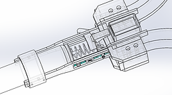
New Canister Interface
After lots of trial and error and test prints, I had settled on a design for the butane release mechanism that safely contained the leaks, and also dynamically controlled the hilt shape. I had also made lots of modifications and adjustments to the structure of the hilt, printing, breaking, then reinforcing.
You can see that the new nozzle is moved by the gears attached to the trigger, and it has 3 paths for the butane to travel down. The main one is meant for when the trigger is fully pulled and the butane is travelling down the center path (shown in red). When the trigger is half pulled, the butane leaks out the sides, but it is contained by this larger interface, and it goes down the side paths (shown in orange), safely out the front of the sword.

Hilt Redesign
The original idea for keeping the majority of the hilt from catching fire was to have CNCed G-10 (FR-4 grade) panels covering the piece, however now that I could print fire retardant pieces, I had the idea of printing pieces that covered the hilt. I was however rather conflicted on what shape the and design the hilt should be. I was debating whether I wanted large cross guard, but I didn't like the way it affected the form of the sword.
I took the idea of having more metal reinforcements from Version 3.0, but this time I wanted the Hilt to be 2 pieces, that fit together in a clamshell design.
I had also figured out exactly how I wanted the hilt to look. I wanted it to be a dynamic piece, that expanded based on the trigger pull. I figured I could do all of these features with a rack and pinion design, that would expand the hilt on both sides evenly, and move the nozzle interface with the canister. I also drew some sketches for how I wanted the hilt shape to look.


Electronic Relocation
For this design I also made sure to relocate the PCB out of the handle, and further into the hilt. I gave it a cover, and added a lever so that the button was more reachable and easy to press. Since the PCB wasn't designed to fit in this space specifically, I might have to think about reshaping it for the future, but for this version. This appears to work nicely.

Testing 4.0
Testing the Gas
Prior to testing, I ensured that the new mechanism wasn't leaking by testing it underwater. The silicone gasket held well, and the triggers functioned as expected. The flame stopped immediately after I released the trigger, and it was now time to mount and wire the electronics, along with the heat shields.
Testing the whole thing.
After preparing a table of fire extinguishers and wet towels, I headed outside to test the design, and it worked beautifully. One of the things that could use a little tweaking though is the canister reload, since the pieces that hold the canister are more brittle in resin, it actually functions a little less smoothly than version 2.0. With some dimensional tweaking this should be solvable though. I also would like to reinforce the handle a bit more as well, while it holds under load, it does bends slightly and could use some reinforcement.
What's Next?
Microcontroller
A change I might like to implement in the future is replacing the PCB and buttons with a microcontroller and accelerometer. I'm still deciding whether I would want the butane controlled by wire though, since that could easily go wrong. But I'm sure I could design around it, or perhaps put some emergency stops in there.
Carbon Fiber
Now that the design is fleshed out and nearing completion, I plan on ordering the tong pieces that make up most of the handle in CNCed carbon fiber plates. This would provide the rigidity and strength that I'm looking for, especially during impacts.
Colored Flames
I've been experimenting with using chemicals inside of the slits to change the color of the flame (at least partially). Currently, I'm coating the blade in a wax mixed with chemical solution. Haven't done any real testing or research on this idea though.
Improve the Blade
If you were to look at this project as strictly a sword, there's lots of room for improvement. It's incredibly heavy and unbalanced. I would like to revisit the blade design and do more research into what makes a practical short sword. Perhaps get a professional to sharpen it.
Blessing
I also intend to get this sword blessed by the Catholic Church.
